Connecting to DC Power Supply
The following table lists the DC power supply specifications:
DC Power Specifications
|
Item |
Description |
|---|---|
|
Power Supply |
Two hot swappable, power supply modules for power load sharing and DC power redundancy in case of failure of one of the modules. |
|
Input Ratings |
Dual universal power supply 40-60 VDC, 17A max. |
|
Connection to Electrical Outlet |
DC power supply inlet. |
|
External Power Cable Connector Type |
DC Power feed using two 48 VDC insulated wires |
|
Safety Standards |
IEC60950-1, UL60950-1 |
| ● | Connection of the device to the DC mains power must be done only by a certified electrician in accordance with local national electrical regulations. |
| ● | Both Power Supply modules (1 and 2) must be connected. Ensure that you connect each one to a different DC power supply source. Two Power Supplies provide 1+1 power load-sharing and redundancy. The DC power sockets are located on the device's rear panel. |
| ● | The two DC power sources must have the same ground potential. |
| ● | The device must be connected (by service personnel) to a socket-outlet with a protective earthing connection. |
| ● | If a failure occurs in any one of the Power Supply modules, replace the module immediately. For replacing the Power Supply modules, see Replacing the Power Supply Modules . |
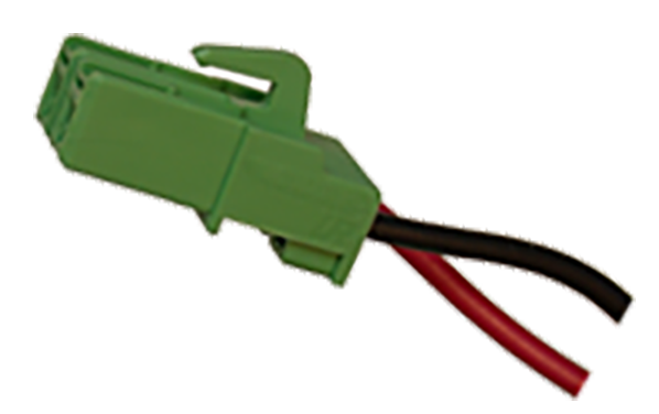
The device is shipped with a DC terminal block pre-installed in the chassis DC inlet on each Power Supply module. The device is supplied with two DC power feed cables terminated with a crimp-connection type DC terminal block for connecting the DC inlets to the DC power source. The cable includes two insulated 14-AWG wires (for positive and negative polarity).
DC Power Feed Cable Terminated with Crimp-Connection Type DC Terminal Block
| ➢ | To connect the device to DC power supply: |
| 1. | Connect the open ends of the two wires on the DC power feed cable (supplied) to the DC power source. Make sure that the wires are connected to the correct polarity (positive and negative). |
Make sure that you connect the DC power feed cable to the power source in the correct polarity. The cable's two wires are color-coded and numbered to indicate polarity:
| ● | Black Wire (1): negative (-) polarity |
| ● | Red Wire (2): positive (+) polarity |
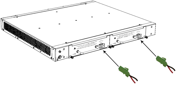
| 2. | Plug the DC power feed cable, crimped to the terminal block, into the DC inlet (labeled DC IN), making sure that the hook on the terminal block snaps into the groove above the DC inlet. The following figure shows the correct orientation of the terminal block to the DC inlet (i.e., hook is above terminal block): |
Connecting to DC Power
| 3. | Verify that the chassis is receiving power - the PWR LED on the Power Supply module should be lit (green). |
| 4. | Repeat the procedure for each Power Supply module. |